How to Prep and Install a Hollow Metal Replacement FRP Door
First, it is important to read all instructions before beginning the installation of your Hollow Metal Replacement Door.
This Hardware Prep and Install Guide will help alleviate hardware prep, hardware attachment, and painting problems caused by the most common errors. It references reinforcement locations, finish recommendations and lock pocket details for our Hollow Metal Replacement FRP Door.
This guide is not a step-by-step, foolproof checklist suitable for every situation.
Follow good practice in hardware prep, door finish, and door installation to ensure you do not void your warranty.
Direct any questions about the prep, installation, or hardware function to your HMR-FRP Door Distributor. You can also download a PDF version of these instructions, and be sure to check out our Lock Pocket Prep and Installation Video below.
Now that we’ve gotten all that out of the way let’s examine how to install a Hollow Metal Replacement (HMR-FRP) Door.
Painting
1. The HMR-FRP Door does not require painting. If you wish to customize the appearance with paint, consult your paint supplier for the best type of primer and paint for painting fiberglass and anodized aluminum. Follow all paint manufacturer’s instructions for prepping and painting. Lightly scuff the entire surface of the door that you want to paint. Be sure to clean any contaminates from the surface before painting and ensure that the door’s surface is clean and dry.
Lock Pocket Prep Instructions
2. To prep for cylindrical locks, mortise locks, and deadbolts, please follow this procedure:
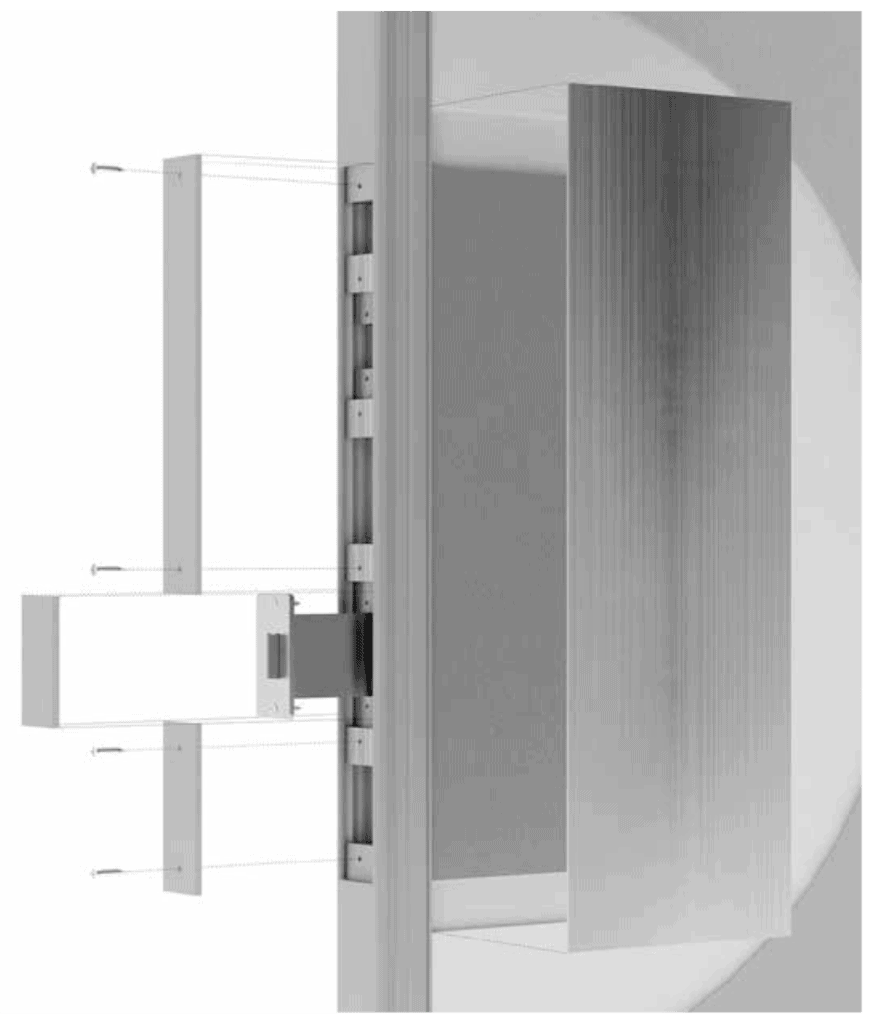
See Figure A below.

A. Remove the lock pocket cover plate on the edge of the door. Locate additional screws included in the foam in the pocket. You will need these screws to secure the cover plate to the lock clips once the latch mechanism/lock body is attached to the latch clips.
Slide three (3) lock clips to the top of the lock pocket and leave one (1) at the bottom.
B. Determine the centerline of the lock and mark the face of the door and the edge of the lock pocket.
C. Prep the face of the door for the cylindrical lock/deadbolt or mortise lock function holes using the manufacturing templates supplied with the device. When installing a mortise lock, you will need to remove some foam to allow the lock body to slide into place. If installing a cylindrical lock or a deadbolt, you will drill a hole through the foam for the latch bolt.
D. Install locking hardware into the prepared cavity and slide a clip up to the bottom of the latch bolt/lock body and down to the top of the latch bolt/lock body. Make sure the prepped holes are properly aligned with the hardware. If needed, use shims to adjust the depth into the cavity. When aligned, use a #25 bit to drill a hole in the clip. Use the supplied screws from the foam to fasten the hardware.
E. Measure from the top of the lock pocket cutout to the top of the latch bolt/lock body. Transfer that measurement to the lock pocket cover, measuring down from one end of the lock cover. Next, cut the lock pocket cover at that mark and attach using one screw removed earlier from the cover. Attach the cover at the top to the clip mounted to the door rail. Drill a 5/32” hole in the other end of the lock pocket cover and the lock clip attached to the latch bolt/lock body. Then, countersink the cover plate, and attach the cover to the clip. Do the same for the bottom cover. Be sure not to cut the end that has the countersink hole for attaching to the clip in the door rail.
Exit Devices
3. Apply exit devices directly to the face of the door by drilling and tapping the aluminum reinforcements and securing them with machine screws. Thru-bolts can also be used. See Figure B showing the location of reinforcements.
Installing Closers and Cuts for Vision Lite Kits

4. See Figure B above, showing reinforcement locations in the door. Use this reference for installing closers and making cutouts for vision lite kits. The hinge stile is 1/8” thick aluminum and is designed for a continuous gear hinge (recommended model SL-11HD). The door can be drilled and tapped to accept the hinge.
IMPORTANT: Do not cut into the aluminum perimeter/ stiles and rails (indicated by dashed lines). It will void the warranty.
Check out our other installation guides, and contact our customer service team if you have any additional questions.
More Hollow Metal Replacement FRP Resources
- Special-Lite’s Hollow Metal Replacement FRP (HMR-FRP) Door was introduced in January. Read the announcement.
- How does our HMR-FRP stack up against a Hollow Metal Steel Door? Read why one is the better door replacement choice.
- Visit our Resource Center to view all documents related to this door.